I've always had a passion for constructing large aircraft, especially sailplanes. Additionally, I have a keen interest in renewable energy sources, such as solar power. This inspired an intriguing concept: combining these interests to develop a solar-powered sailplane.This project embodies the fusion of my enthusiasm for aeromodelling and solar energy.
Fabrication
After the model is modified to meet the specific outline dimensions, shape, and component layout, attention turns to choosing the correct materials. Balsa wood as the top choice due to its light weight, strength, and cost-effectiveness, making it perfectly suitable for such projects. Next, the airfoil and other vital parts are precisely laser-cut, ensuring each component is made with the utmost accuracy.
The wing is constructed by glueing the laser-cut ribs to the main spar. A 16mm aluminium tube is utilized to reinforce the strength of the wing, providing necessary support and rigidity. Following the wing assembly, the fuselage is assembled by attaching formers and stringers. This step creates the basic shape of the fuselage, which is subsequently covered with balsa sheets, completing the primary structure of the model.
Layout of a Solar-Powered UAV System
Integration of Solar Cells into Wing
Each solar cell is individually tested for defects. After identifying and segregating the functional cells, they are arranged in a 2x2 configuration on a lamination sheet. These cells are then laminated using a standard laminating machine, a process that is repeated to produce a total of six panels. Once assembled, each solar panel is tested individually to ensure proper functionality.
The solar panels are connected in series to boost the voltage to approximately 26 volts. After thorough testing of this configuration, the panels are methodically adhered to the airfoil ribs. The wiring is carefully integrated within the wing, with the main positive and negative terminals accessible at the wing's connecting portion, facilitating easy assembly and maintenance.
Incorporating a Flight Control System
The Pixhawk flight controller is integrated into this solar-powered plane to gain insights about power consumption, battery information, solar power input from the wings, and location details. This integration not only facilitates the collection of critical data but also contributes to making the plane autonomous.
I have utilized the Holybro Pixhawk 2.4.6, a 3DR GPS module, and two types of telemetry: The SiK Telemetry Radio V3, and the standard 915MHz telemetry unit. Additionally, a power module is install to power the entire system and monitor the power flow. The inclusion of these components ensures that all necessary power metrics are observed and managed efficiently, allowing for a seamless operation.
Bench Testing
In the testing phase, I tested the BLDC motor with various propellers to find the optimal thrust-to-power ratio using a DIY thrust stand and a watt meter. The 18x9 inch propeller paired with the 360Kv motor produced the best results, achieving 1200 grams of thrust at roughly 130 watts. I then tested the solar output from the wing, which was suboptimal due to the presence of many cracks in the way the solar panel sheet was built. Using an MPPT compatible with a 4s Lipo battery, the solar wing charged the battery at 3 amps or 51 watts, taking 1.1 hours to charge a 4000mAh 4s battery from 11 am to 3 pm.
Upon integrating all systems for a bench test, I found that without the solar wing, the motor running at 50% throttle consumed 80 watts and operated for roughly 45 minutes solely on battery power. However, when the solar wing was engaged, the motor’s run time extended to approximately 104 minutes—more than twice the duration without solar assistance. This significant increase highlights the solar wing’s effectiveness in prolonging operational duration and enhancing the system’s overall efficiency.
Maiden Flight
On the morning of April 11, 2022, at 10:21 AM, we conducted our initial maiden flight test, which lasted two minutes. The objective was to observe the model's gliding capabilities and flight characteristics, and to verify that the flight controller was receiving data accurately. Before the flight, we performed several hand-launch glide tests; these were very promising, confirming the model's stability and glide efficiency.
The following day, we conducted our flight test near Chennai at 8am in somewhat gusty wind conditions. The sailplane maintained flight for about 74 minutes, marking a 64% increase in endurance compared to our static bench test. This improvement further validates the enhanced performance of our system in real-world conditions.
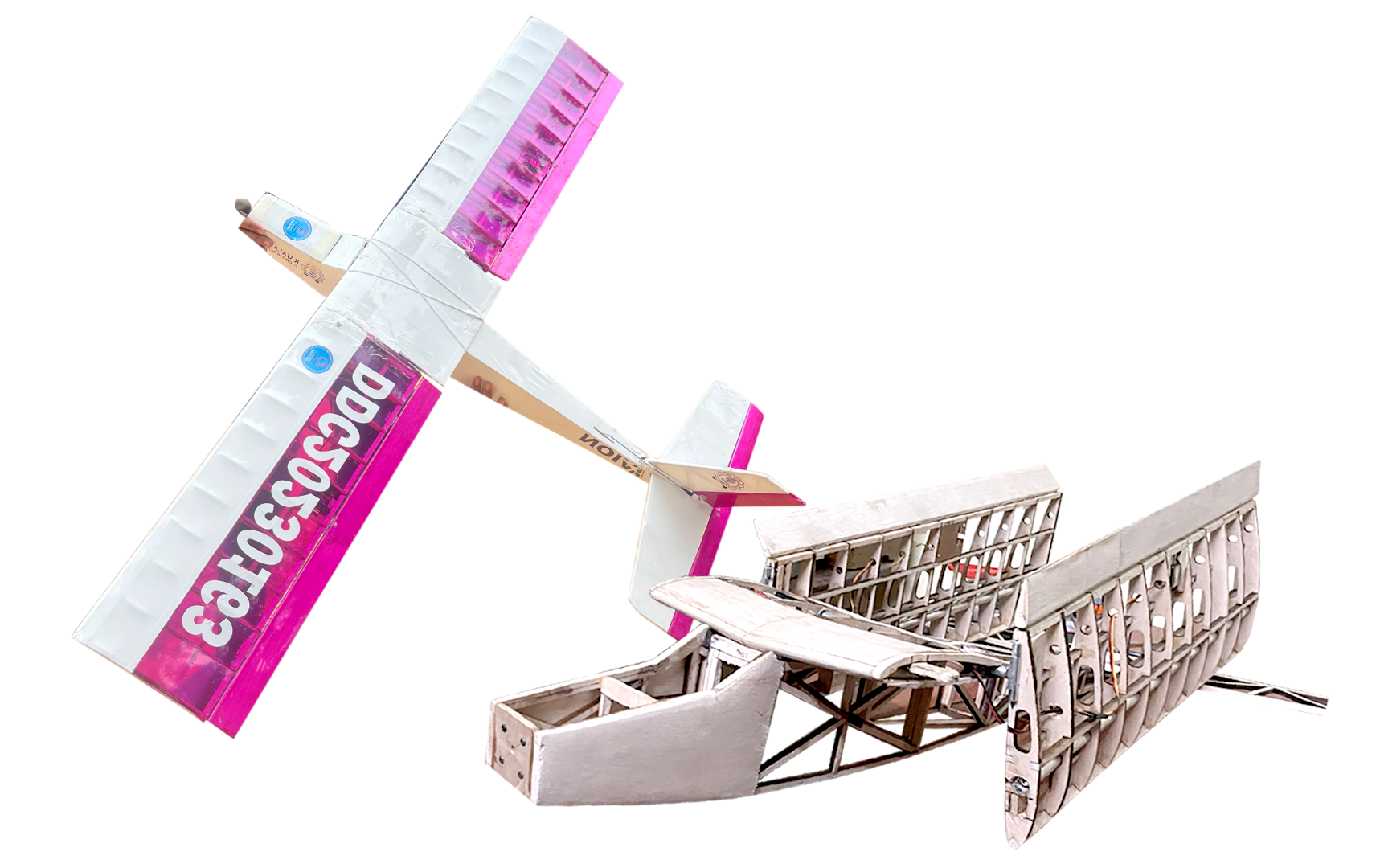
3rd Flight Crashed
I'm not sure why the plane crashed it might be because of our poor flying experience and the control surfaces area was too so we where not able to recover the model from tip-stall (and the altitude was also less)
Only the left wing was damaged and the tailportion
After this crashed I converted the Solar-sailplane to a regular sail plane
After the successful proof of concept, I realized the potential of this approach despite the initial challenges. In the first version, I encountered several issues with the solar array—cracks/air bubble appeared in the solar cells during fabrication, and there were problems with the electrical components as well. Determined to overcome these challenges, I initiated VERSION-2 as part of my own project and ultimately chose to develop it further as my college Final Year Project.
Solar Avion Version 2 - (2022-present)
Layout of a Solar-Powered UAV Version-2
Introduction
The aim of VERSION-2 is to rebuild everything from scratch—from the initial design to the final assembly—to ensure that the solar array operates at maximum efficiency. This version will focus on eliminating issues like cracks and air bubbles in the solar cells, developing a custom Li-ion battery pack, and incorporating several other improvements. The ultimate goal is to enable the plane to achieve a continuous flight time of at least 12 hours.
Fabrication - Photos & Videos
Solar Encapsulation
One major upgrade from the first version of the UAV involves encapsulating the cells to prevent air bubbles and cracks, ensuring an even finish throughout the wing. Initially, I attempted to encapsulate the cells at home by using a vacuum cleaner to remove air from one side while applying heat with a hot air gun on the other end. This method was successful for a 4-cell setup but proved ineffective for a 12-cell configuration. Consequently, I decided to use a commercial encapsulation machine. I discovered an MSME owner near Mumbai who offered to assist me, so I gathered all the required materials and went to his facility for support.
Encapsulation video
One major problem with this encapsulation method is that it almost doubles the weight of each cell, and auxiliary support. I used a backing white layer and EVA sheets on both the top and bottom of the cells. However, when the cells are exposed to heat, the EVA starts to melt, causing the surface to stick and allowing numerous dust particles to adhere. This significantly reduces efficiency. To prevent this, I had to add protective layers, such as a thin transparent plastic sheet, but this solution adds even more weight—approximately 100 grams.
Update Soon
fixed Wing
Foldable Wing Plane
This aircraft won 1st prize in the SAE DDC Competition for its ability to feature foldable wings and a locking mechanism in a micro-class plane (1.4-meter wingspan). Click to explore further details.